A current limiting resistor will need to be added in series with the LED to limit the on current to 300ma. Do not make the mistake of setting the average current to 300ma as this will damage the LED.
For example if the circuit is running at 10% output, the pulses would be 300ma at 10% of the time so the average current would be 30ma.
Halogen to LED conversion help
-
Technician1002
- Captain

- Posts: 5189
- Joined: Sat Apr 04, 2009 11:10 am


I would not have much faith in something that has a blatant pin out error.
Two wrongs does not make it right.
Try the same schematic with YENKA.
Two wrongs does not make it right.
Try the same schematic with YENKA.
-
MrCrowley

- Moderator

- Posts: 10078
- Joined: Fri Jun 23, 2006 10:42 pm
- Location: Auckland, New Zealand
- Been thanked: 3 times
I understand this is what I need:
http://shop.aaaa-electronic.de/epages/1 ... ducts/M171
They had them at the store but without a price, judging by similar kits I assume they are about $30-$50USD. Seems like it would be perfect if it wasn't for the price.
The staff at the store were hopeless.
Edit: While i'm at it, what about these:
http://www.jaycar.co.nz/productView.asp?ID=AA0593
http://www.jaycar.co.nz/productView.asp?ID=AA0596
If links don't work, search:
Dimmable Constant Current LED Driver Module
12-30VDC input LED Driver
Edit 2:
@dewey1,
Assuming I went with a bulb like you suggested on the first page, what kind of LED bulb can I use that can be interchanged with the halogen (so the original microscope dimmer and on/off switch still works)? I've found some that are 240v but only 6W or so. Even if I found one that is 110v, how low of a wattage can I get away with?
-
MrCrowley
- Moderator
- Posts: 10078
- Joined: Fri Jun 23, 2006 10:42 pm
- Location: Auckland, New Zealand
- Been thanked: 3 times
Okay so I hooked up a temporary circuit.
I have a 330R resistor connected to the negative from the power adapter before it goes in to the LED driver board and both positive and negative wired to a 5k potentiometer before the driver board. It dims perfectly giving me a great range. Tomorrow I will test for any IR emittance, if it isn't too noticeable on video I'm happy.
Thanks for all the help so far. I know i'm not doing things the right way, the sensible way, but if it can save a poor student $50 I'll live with it
Edit: Should I worry about any IR/UV light when I look through the microscope eye piece? Some people say it's fine, others say to always use a video camera or such.
-
Mr.Tallahassee

- Specialist 3

- Posts: 364
- Joined: Sun Jul 10, 2011 2:35 am
A PMW costs ten or so dollars to build. Saving money shouldn't be hard unless you build it without the IC. Of course, who would even try?
As to the IR/UV light, LEDs normally don't put out enough IR or UV (unless they're made to) to harm your eyes. I would try to limit it though. You never know for sure.
As to the IR/UV light, LEDs normally don't put out enough IR or UV (unless they're made to) to harm your eyes. I would try to limit it though. You never know for sure.

A white LED is a blue LED chip with a phosphor coating to add a yellowish red band into the mix. This combines to form what appears to be white light. White LEDs, to my knowledge, do not put out any significant IR nor UV. However, they do have a sharp peak in the deep blue end of the spectrum, which could possibly be a bad thing if you expose yourself to too inense a source. Here's the spectrum of a white Luxeon LED: http://ledmuseum.candlepower.us/sixth/desk.gif
I wonder how much deeper the ocean would be without sponges.
Right now I'm having amnesia and deja vu at the same time. I think I've forgotten this before.
Add me on msn!!! insomniac-55@hotmail.com
Right now I'm having amnesia and deja vu at the same time. I think I've forgotten this before.
Add me on msn!!! insomniac-55@hotmail.com
-
MrCrowley
- Moderator
- Posts: 10078
- Joined: Fri Jun 23, 2006 10:42 pm
- Location: Auckland, New Zealand
- Been thanked: 3 times
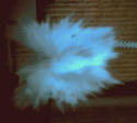
I've finished the mod for LEDs which works great but I'm getting a weird pink hue on the sides of images when using the HD webcam missing the IR filter.
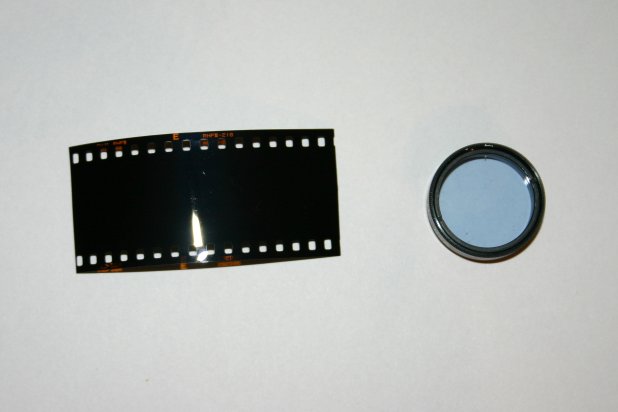
I removed a bunch of filters from a SharpVision slide projector. I got what appear to be 2 polarizing filters and 3 unknown filters. I'm hoping one of them is the IR cut filter.
The photo "normal" shows what I see on my computer when using the webcam. Normal colour in the middle with pink colour on the sides. The three photos titled "filter 1", "filter 2" and "filter 3" and the three filters from the SharpVision. Two of them don't seem anything like IR filters and one of them has little effect. I'm beginning to think that maybe this pink hue on the images isn't actually IR but there is a problem somewhere else.
The three filters were found stacked in a row at a 45 degree angle to the light source. After that came a polarising filter, some mirror like thing connected to the circuit board which must project the image and then a second polarising filter before the lens.
- Attachments
-
- filter 3
-
- filter 2
-
- filter 1
-
- Normal
-
Technician1002
- Captain
- Posts: 5189
- Joined: Sat Apr 04, 2009 11:10 am
A camera IR filter often has a bluish tint to it in the visible spectrum. Removing it without changing the color balance on the camera will produce orangish photos such as your filter2 photo. On a single pickup CCD, (without a beamsplitter and 3 pickups, IR tends to show up as a green color in the photo much like the Sony Night Vision mode with white or IR.
Weird colors in the other photos can be a result of polarization artifacts as many cameras have an internal filter.
The two two polarizing filters can be used to look for items that change the polarization.. This can change the amount of light permitted to pass through two polarizers depending on the material in between. This is how a LCD display functions. With one or both polarizers missing, there is no image.
A example photo of plastic under stress between two polarizers can show the stress in the plastic as it changes the passing light.
-
MrCrowley
- Moderator
- Posts: 10078
- Joined: Fri Jun 23, 2006 10:42 pm
- Location: Auckland, New Zealand
- Been thanked: 3 times
Are you talking about an IR cut-off filter (heat-absorbing filters) or one that allows IR but blocks visible light (cold filter)?A camera IR filter often has a bluish tint to it in the visible spectrum. Removing it without changing the color balance on the camera will produce orangish photos such as your filter2 photo
I'm just a little confused about your wording because I'm not removing a filter from the webcam to achieve the orange photo, I'm holding a filter in front of it. Changing the white balance while holding the orange filter (filter 2) in front of the webcam (which has no lens or IR cut-off filter, just the sensor) only changes the colour from orange to purple to blue to yellow to red to whatever, i.e., I can't get white.
An internal filter built in to the circuitry or on the sensor?Weird colors in the other photos can be a result of polarization artifacts as many cameras have an internal filter.
What items do you suggest I should test to see if they are changing the polarization?The two two polarizing filters can be used to look for items that change the polarization.. This can change the amount of light permitted to pass through two polarizers depending on the material in between. This is how a LCD display functions. With one or both polarizers missing, there is no image.
Sorry if I misunderstood your post, just wasn't sure if we were on the same page.
Edit: Okay, just did a test with the webcam and a TV remote. None of the three filters block IR. Is there a chance the IR filter for the SharpVision slide projecter is inside the lens itself and the three random filters are merely to change the colour of the light from the light source before they are projected on to a slide?
-
Technician1002
- Captain
- Posts: 5189
- Joined: Sat Apr 04, 2009 11:10 am
I think your last edit is on the money.
To test if a camera has an internal polarizer, rotate a polarized lens in front of it and see if the lens darkens and lightens as it rotates. If rotation has no effect, the camera is not filtered. Most are not filtered.
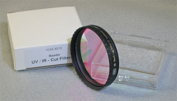
The IR filter in a camera is on the sensor, is bluish in color, and is an IR cut filter.
To test if a camera has an internal polarizer, rotate a polarized lens in front of it and see if the lens darkens and lightens as it rotates. If rotation has no effect, the camera is not filtered. Most are not filtered.
The IR filter in a camera is on the sensor, is bluish in color, and is an IR cut filter.
-
MrCrowley
- Moderator
- Posts: 10078
- Joined: Fri Jun 23, 2006 10:42 pm
- Location: Auckland, New Zealand
- Been thanked: 3 times
Ah, that is smart. I gave it a go and no change was obvious.To test if a camera has an internal polarizer, rotate a polarized lense in front of it and see if the lens darkens and lightens as it rotates. If rotation has no effect, the camera is not filtered. Most are not filtered.
I thought it was the IR-pass filters that looked blue? I had followed several different articles on modifying the webcam and they all said I would have to replace the IR cut-off filter as it would be removed and it appeared I did remove the one from my webcam as it was glued to the back of the lens mount, it's colour was similar to this. I can't test it to see if it stops IR because I can't remove it from the lens mount without damaging it.The IR filter in a camera is on the sensor, is bluish in color, and is an IR cut filter.
If you are right and the IR cut-off is on the camera sensor, I just need to figure out what is causing that pink hue on the sides of the image.
Thanks for your help so far.
The IR cut filters either appear pale turquoise or ruby red, depending on how they're viewed. Looking through one it will have a blue tint, while light reflected from the filter will be red (as it reflects deep red and IR light to function).
I wonder how much deeper the ocean would be without sponges.
Right now I'm having amnesia and deja vu at the same time. I think I've forgotten this before.
Add me on msn!!! insomniac-55@hotmail.com
Right now I'm having amnesia and deja vu at the same time. I think I've forgotten this before.
Add me on msn!!! insomniac-55@hotmail.com
-
MrCrowley
- Moderator
- Posts: 10078
- Joined: Fri Jun 23, 2006 10:42 pm
- Location: Auckland, New Zealand
- Been thanked: 3 times
Interesting. With my back to the window (only source of light in the room), holding up one of the filters in front of me shows the reflections as blue and looking through it everything is orange. Does that make it an IR-pass filter? 
-
Technician1002
- Captain
- Posts: 5189
- Joined: Sat Apr 04, 2009 11:10 am
Their are several different ways those filters are manufactured which affects their response in the visible spectrum. They are cataloged in two major camps.
Thin layer Dichoric filter. This filter absorbs very little light, but reflects some wavelengths while passing others. These are easily identified by the reflected image is a complimentary color to the pass image. They work by reflection of the unwanted color. The color will have a shift as the angle of the filter is changed. This may be the source of the pink edges in the photo above.
http://en.wikipedia.org/wiki/Dichroic_filter
The less expensive filter is an absorption filter.
This filter is simply colored glass formulated to absorb and block the passage of the unwanted color. This filter does not have a color shift with a change in angle and does not have a strong colored reflection.
The absorbtion filter is more difficult to get a sharp cut off response than the thin layer filter. The thin layer filter is more expensive to manufacture as it is most often built by depositing many layers of 2 or more clear films of different optical densities to create a selective frequency to reflect.
Custom colors can be produced of any wavelength using the thin layer filters. Dye based absorption is limited to the range of chemicals used to dye the glass. Dye based filters can fade. Thin layer filters are noted for their long life and stability.
-
MrCrowley
- Moderator
- Posts: 10078
- Joined: Fri Jun 23, 2006 10:42 pm
- Location: Auckland, New Zealand
- Been thanked: 3 times
Well that sounds like that orange filter I have. Unfortunately it's not the source of the pink edges as that photo (normal) is without any filter being used.Thin layer Dichoric filter. This filter absorbs very little light, but reflects some wavelengths while passing others. These are easily identified by the reflected image is a complimentary color to the pass image. They work by reflection of the unwanted color. The color will have a shift as the angle of the filter is changed. This may be the source of the pink edges in the photo above.
I'm wondering now if it might be something to do with the LED collimator or not enough illumination. Although I seem to have more than enough illumination even at the highest magnifications.