Launching circuit - cool and simple?

A place for general potato gun questions and discussions.
User avatar
Davidvaini
Sergeant 4
Sergeant 4
Posts: 1315
Joined: Tue May 29, 2007 8:58 pm

Fri May 27, 2011 11:51 am

Hey guys, I am working on a firing control for a launcher I am working on.

I basically got the device to have 1 switch that is an on/off/on switch that acts as a safety/fire mode. It would be considered on safety when it is in the off position (the middle) and when it is to the right, it would be firing mode. When it is on the left however I want it to be on "charge" mode.

There would be another "plug in" in the the middle where I can plugin a charger and charge the battery while the battery is inside the gun. That plug would also double as another switch when I have the safety switch turned to firing mode. The plugin would allow you to plugin another switch like my remote firing keychain switch. Last but not least, would be a firing button. This button would be the button you would press to fire the gun without any plugin switch.

So in normal firing mode, you would switch the safety to firing mode, make sure you have a little plugin that just completes the circuit, and you would just push the firing button.

In Charging mode, you would switch the safety to charging mode, make sure you have your charger plugged into the plugin, and it will start charging.

In "remote firing mode" make sure you have the switch to the firing mode, and plugin your remote firing trigger such as a remote start keychain or other seperate circuit. but here is the kicker, I still have my firing button the the launcher and unless I make that a on off on switch I dont see how i could fire this thing remotely since I would have to also push the firing button. I was thinking about making the button removeable just like the "plugin part" so then I could just put a thing to complete the circuit as well, but then that makes setup a little bit longer. and as far as a on/off/on switch for firing the gun, I would rather have a push button then a switch.

Here is the circuit I drew up real quick, please let me know what you think.

Image

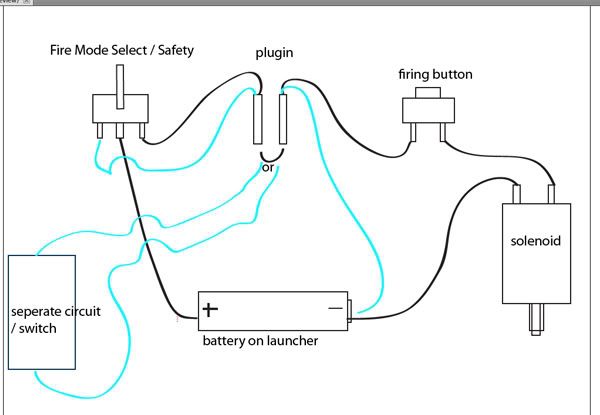
The separate circuit would be optional and not always pluged in, it would only be plugied in when i flip the fire mode to the left, and when that little wire to complete the circuit inside the pluin is taken out. thus that is why the word or is there, not to act as an or gate. There is no or gate. The blue wires going from the plugin to the battery andthe plugin to the fire mode switch however would always be there.

let me know if you see any problems with this circuit.
User avatar
Technician1002
Captain
Captain
Posts: 5189
Joined: Sat Apr 04, 2009 11:10 am

Fri May 27, 2011 1:07 pm

The safety is often a guarded switch of some kind to prevent accidental actuation or operation by uncertified individuals. A key switch or a guarded toggle switch is often used. Either a key is needed or a cover over the switch needs flipped up to operate the switch. For DC a diode is recommended in parallel with the solenoid. An AC solenoid operated on DC does not need the diode due to the reluctance ring in the solenoid.
Image
Image
Image
User avatar
dewey-1
Sergeant 3
Sergeant 3
Posts: 1298
Joined: Wed Mar 28, 2007 10:24 am
Location: NE Wisconsin USA

Fri May 27, 2011 1:37 pm

I recommend this free program if you would like to make decent schematics.
It is easy to learn. I have used it for both schematics and PCB layouts.


http://www.expresspcb.com/expresspcbhtm ... ftware.htm
User avatar
velocity3x
Corporal 4
Corporal 4
Posts: 828
Joined: Fri Jun 05, 2009 3:09 pm
Location: Yuma, Arizona
Contact:

Fri May 27, 2011 2:09 pm

________________
A government big enough to give you everything you want is big enough to take everything you have.
Attachments
Switch Guards.jpg
Switch Guards.jpg (25.67 KiB) Viewed 4581 times
User avatar
al-xg
Corporal 2
Corporal 2
Great Britain
Posts: 643
Joined: Fri Jan 19, 2007 12:29 pm

Fri May 27, 2011 2:51 pm

I'm guessing he was thinking more along these lines
Image

I've used a similar circuit for safe/semi/full auto on a few electro-pneumatic prototypes.

On the next version when ever that happens, there will be other bits added to the circuit (pressure control, breach open protection etc...), and I'll probably use a rotary switch for the selector, just because it's cool.
User avatar
Davidvaini
Sergeant 4
Sergeant 4
Posts: 1315
Joined: Tue May 29, 2007 8:58 pm

Fri May 27, 2011 4:27 pm

no not really, i guess I didnt explain myself clearly enough...

Im going to use an on/off/on switch - not momentary. This would be for 3 different modes - 1. Charge Mode, 2.Safe Mode, 3, Firing Mode.

Then additionally I will have a plugin port where I can plugin an on.off switch if I want to or plug a charger to charge the battery, otherwise, it will just have a wire so it completes the circuit.

Then finally I will have anther switch which is just a firing button.


And I am using a DC battery on an AC solenoid valve so that should be fine, I am just wondering if the circuit looks okay, or not.

This is the switch I was going to use: http://www.allelectronics.com/make-a-st ... TCH/1.html

and I was going to put a guard on it. so that is all taken care of, I am just wondering if there will be a problem with the wiring or the switch. The switch if I am correct has 3 positions. Left(On), Center (OFF), right(on) left and right are seperate circuits with middle being the common ground? So if I flip the circuit to the left it allows elecriticy to flow from the middle to the left, and if I flip the switch in the middle it does not allow electricity to flow through at all.. and if I flip it to the right it allows electricity to flow from the center to the right prong correct?
User avatar
dewey-1
Sergeant 3
Sergeant 3
Posts: 1298
Joined: Wed Mar 28, 2007 10:24 am
Location: NE Wisconsin USA

Fri May 27, 2011 7:26 pm

Here is a schematic for the control.

Updating schematic!
Last edited by dewey-1 on Fri May 27, 2011 8:05 pm, edited 1 time in total.
User avatar
Davidvaini
Sergeant 4
Sergeant 4
Posts: 1315
Joined: Tue May 29, 2007 8:58 pm

Fri May 27, 2011 7:33 pm

dewey-1 wrote:Here is a schematic for the control.
now if only I could understand it :D
Last edited by Davidvaini on Fri May 27, 2011 7:40 pm, edited 3 times in total.
User avatar
dewey-1
Sergeant 3
Sergeant 3
Posts: 1298
Joined: Wed Mar 28, 2007 10:24 am
Location: NE Wisconsin USA

Fri May 27, 2011 7:37 pm

Your pictorial is actually wrong but the schematic is correct!
User avatar
Davidvaini
Sergeant 4
Sergeant 4
Posts: 1315
Joined: Tue May 29, 2007 8:58 pm

Fri May 27, 2011 7:40 pm

dewey-1 wrote:Your pictorial is actually wrong but the schematic is correct!
okay, quick question, why does there have to be a diode with the solenoid? I have not had to do this before with a sprinkler valve solenoid when running a DC battery... I mean I understand so it doesnt send any EMF back, but yeah...

I think I am understanding the diagram a little bit more now.. ill try to redraw it with my own "diagram" style so I can figure out if I truly understand it.

Another quesiton, the plugin area, i want to be able to plugin another switch there if to fire the device, would i still be able to do that? Or would I have to put a jumper or make sure both switches are pressed?
User avatar
Technician1002
Captain
Captain
Posts: 5189
Joined: Sat Apr 04, 2009 11:10 am

Fri May 27, 2011 7:56 pm

Actually the schematic is incorrect. The external jumper needs to go between the switch and solenoid. In it's current location, it will short out the battery and run it down. If a high current battery is used, you may start a fire. This condition will happen when P1 and J1 are joined and the switch is in the safe position.

A separate battery charger jack is needed that is not the same as the safety interlock jumper.

I was in a class when an instructor made that type of error and someone shouted "Quick, erase that before you start a fire". Everyone laughed.
Last edited by Technician1002 on Fri May 27, 2011 8:00 pm, edited 1 time in total.
User avatar
dewey-1
Sergeant 3
Sergeant 3
Posts: 1298
Joined: Wed Mar 28, 2007 10:24 am
Location: NE Wisconsin USA

Fri May 27, 2011 8:00 pm

Here is a good explanation about suppression diodes on solenoids.

http://instrumentation.web.id/?p=489

For a remote switch to work it has to be connected in parallel with the other Fire switch.

Tell me which parts are actually on the cannon and functions you actually want to do remotely or are you trying to do Arm and Fire remotely?

Yes Tech I had a DAA (dumb a$$ attack) when I did that. I will redraw and repost later.
User avatar
Davidvaini
Sergeant 4
Sergeant 4
Posts: 1315
Joined: Tue May 29, 2007 8:58 pm

Fri May 27, 2011 8:06 pm

here are the scenarios I want to accomplish:

1. switch 1 - switch it to the left and plugin the charger to the input and charge the battery

2. switch 1 - switch it to the middle and plugin the jumper into the input and it will not allow you to fire the cannon

3. switch 1 - switch it to the right and plugin the jumper and press the fire button to fire the cannon.

4. switch 1 - switch it to the right and plugin another switch into the input. This switch could be like a remote keychain start - 12vdc in and 12vdc out or another on/off switch. When this switch is activated it and the fire button is pressed down it will fire the cannon.

Those are the scenarios I want to work.

So the plugin does two things, either another switch can be plugged in (switch 1 would have to be to the right) or it can accept a charger for the battery(switch 1 has to be to the left)


The things on the cannon are everything except the jumper and the remote switch. (two devices that plugin into the plugin.) and the remote switch is just like an on/off switch.

So on the cannon, 2 switches and a plugin. and an external switch can and will be hooked up to the plugin. A charging unit has to be able to plugin to that plugin as well.
User avatar
Technician1002
Captain
Captain
Posts: 5189
Joined: Sat Apr 04, 2009 11:10 am

Fri May 27, 2011 8:23 pm

DC coils have a high number of turns and thus high inductance. They almost always require some sort of suppression to limit the rate of current decay and thus the peak voltages generated.

AC coils have fewer turns for the same voltage because the inductance limits the time the current can increase on a half AC cycle. In addition to the inductance, many AC solenoids and relays have a "Shaded Pole" where a part of the core is separate and has a shorted winding (often a single turn like a wedding ring) which "Shades" the pole.

This shaded pole is used to keep up the magnetic attraction when the coil current passes through zero and provides magnetic pull so the relay or solenoid does not buzz or chatter.

The shorted pole also provides a snubber effect which is why AC relays don't need the diode that is needed on DC relays and solenoids.

The shaded pole limits the maximum rate the relay or solenoid can cycle.

By the same token the diode on a DC relay or solenoid will allow the current to flow after the voltage is removed. This too limits the speed at which the relay or solenoid can release.

For solenoids that must cycle quickly such as a car fuel injector, a resistor in addition to the diode is used to quickly reduce the current when switched off. Other snubber circuits include Zener diode clamping, resistor and a capacitor, or clamping to a voltage rail with a diode.
User avatar
Davidvaini
Sergeant 4
Sergeant 4
Posts: 1315
Joined: Tue May 29, 2007 8:58 pm

Fri May 27, 2011 8:45 pm

okay, I think I am finally starting to understand electronics a lot more, I have had no training whats so ever, so please excuse my ignorance on the topics. I do however try to keep an open mind and I appreciate all your guy's help.

I cant wait to see dewey's new diagram after reading the different scenarios that I need to happen.
Post Reply