Page 4 of 6
Posted: Thu Jun 28, 2012 3:48 pm
by dewey-1
wyz;
Why is the red lead hooked to the - of the capacitor?
The reason for only .7 volts is because you had the diode in backwards.
The real original problem is you have the red and yellow reversed at the capacitor.
The diode is there for suppession with an inductive load like a relay.
It protects the transistor (Q5) on the circuit board.
Posted: Thu Jun 28, 2012 4:03 pm
by wyz2285
It's putting 2.5v now, so I resumed that everything are ok now, so the side of the capacitor with a colored line it's negative? I thought that was the positive, what a fail

Posted: Thu Jun 28, 2012 4:18 pm
by dewey-1
Just because you have 2.5V does not mean anything!
What is the voltage when you actuate the doorbell?
Posted: Thu Jun 28, 2012 4:36 pm
by wyz2285
actually about the same, because I was using rechargeble batterys, they are only 1.2v not 1.5v.
Posted: Thu Jun 28, 2012 5:11 pm
by dewey-1
wyz;
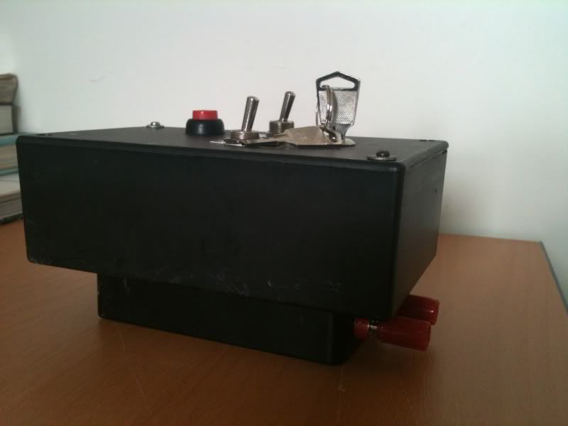
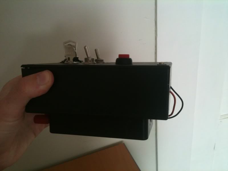
Add a new picture of what you have now to the posting with your other pictures.
Posted: Thu Jun 28, 2012 6:09 pm
by wyz2285
Ok, added.
Message too short.
Posted: Thu Jun 28, 2012 6:19 pm
by MrCrowley
Do you expect the stungun to be triggered by 2.5v or do you just have it wired that way to see if it would? You definitely have it wired different to me as I had the negative pole of the diode wired to the positive from the capacitor and the positive pole of the diode wired to the negative from the cap. Not sure if you've been told to wire it this way or if it's supposed to be wired that way for your circuit, I'm just pointing it out.
edit: did you try those website links I posted? Here, anyone can make an account and buy from element14/farnell or RS-Components. I think element14/farnell wanted a company name so I gave them my parents
holding's 'company'; which is not really a company at all.
Posted: Thu Jun 28, 2012 8:14 pm
by jimmy101
We need to rethink this a bit I think.
Is the doorbell remote battery powered at 3V? If it is then the speaker is being powered with, at most, a 1.5V AC signal with a 1.5V DC offset. That is, the speaking is seeing something like a sine wave (or square wave) going from 0V to 3V. The speaker is an inductive load, since it is an electromagnet, so the circuit can already handle that much of an inductive load.
You want to use the speaker's AC signal to power a switch that in turn controls the 9V DC powered stun gun.
First solution is a low voltage relay. But it'll have to work on the 3V AC signal. Put it into a DC relay and you'll by pulling the relay on and off at whatever frequency the circuit uses to drive the speaker (WAG it at about 1KHz.) A relay might actually cycle at that frequency, and it might not. If it does then the stun gun is being cycled at that frequency. Another WAG, the stun gun won't work like that.
So you need a way to take the 3V AC and use it to trigger some sort of a timer or you need to take the 3V AC signal and smooth it out, probably to 1.5V DC, and use that for a relay or a transistor or an opamp or ... something that can control the 9V (at whatever current) the stun gun uses.
The May 2012 issue of "Nuts and Volts" (
http://nutsvolts.texterity.com/nutsvolt ... rking#pg40) has a circuit that uses a microphone to turn on a laser to help park your car in the garage. Same basic problem as you have: an AC (audio) signal needs to control a DC circuit. They just used an opamp, diode, simple RC network (resistor + capacitor) and a MOSFET (BS170). In the posted circuit I think the first amp could be eliminated. Still, the circuit seems more complex than what is needed.
Seems to me that a cap (used as an integrator) fed into the base of a resistor should smooth the AC and switch the stun guns 9V. Below is a rough digram. The upper panel shows a trace of a 3V 1KHz signal from the door bell, the lower trace is the current through the transistor, and hence the stun gun. I modeled the door bell being on for 50mSec. The on time time doesn't matter much.
The box on the left is the door bell. "Speaker_plus" is the wire to the speaker that isn't connect to that circuit's ground (the battery negative). The box on the right is the stun gun "circuit". Basically the transistor and its guard diode (D2) would be wired in between that circuits negative trace and the battery negative. The guard diode might not be needed but just in case the stun gun is very inductive it'll keep the transistor from getting cooked when the stun gun is turned off. All of the grounds (downward pointing arrows) are connected together and the battery minus from both circuit are connected to together.
I've not tried this circuit. The resistor, cap and diodes are probably about right. I don't know if the 2N222 will supply enough current for the stun gun. In my simulation it supplies about 190mA.
Posted: Thu Jun 28, 2012 8:39 pm
by dewey-1
wyz;
What you have shown in the last picture will not work properly.
I can not tell how you have the stun gun circuit wired.
Where does the white and red wire go?
You may have already damaged Q5 on the circuit board.
Here is a simple schematic attached.
@jimmy101;
Read this article
http://www.hackersbench.com/Projects/di ... /main.html
Here is a good price for US purchases.
http://www.walmart.com/ip/Heath-Zenith- ... r/15719340
Posted: Fri Jun 29, 2012 3:07 am
by wyz2285
I connected the stun gun just to see if there is any spark, I can remove it. I hope I didn´t damage the Q5, the circuit still works fine if I put everything back

I didn´t understand the schematic, where does the batery negative goes and what means YEL and where is it in the circuit?
Posted: Sat Jun 30, 2012 9:01 pm
by MrCrowley
Update:
The doorbell circuit now runs on 4.5V; two diodes in reverse are used to drop the voltage down to ~3.3V for the doorbell circuit and the negative pole of the capacitor is now wired to ground (battery) and the positive pole of the capacitor is now wired to the negative pole of the relay like in
this guide.
I also had to add the stungun circuit to a separate project box as when I had all the components stuffed in one box, the stungun would short out and cause problems (and eventual failure) with the doorbell circuit.
Posted: Sat Jun 30, 2012 9:39 pm
by dewey-1
wyz2285 wrote:I connected the stun gun just to see if there is any spark, I can remove it. I hope I didn´t damage the Q5, the circuit still works fine if I put everything back
I didn´t understand the schematic, where does the batery negative goes and what means YEL and where is it in the circuit?
BLK =Black
BRN =Brown
RED =Red
ORG =Orange
YEL =Yellow
GRN =Green
BLU =Blue
VIO =Violet
GRY =Gray
WHT =White
YEL is the Yellow speaker lead that goes to Q5 on the board. (This is the relay coil negative lead)
ORG is the relay coil plus lead that goes to the plus 6 volt battery.
wyz; all the schematics and circuits I have done for you, you should be able to understand them. Schematics are an international representation of a circuit.
Battery negative is the Black lead.
Posted: Sun Jul 01, 2012 1:09 pm
by wyz2285
Thank you, sorry I´m not very sensitive when come to electronics

Posted: Mon Jul 02, 2012 1:27 am
by jackssmirkingrevenge
wyz2285 wrote:what means YEL and where is it in the circuit?
It indicates parts that are so frustrating to put together that they make you shound

Posted: Mon Jul 02, 2012 8:39 am
by wyz2285
I found a 3v relay, and a 6v one. I bought them both because I´d like to use the 3v one but in case it doesn´t I have the 6v one.