Posted: Thu May 03, 2012 1:44 pm
Here's the tag disassembled, unfortunately as is the board won't fit in the dart type projectile I had in mind, unless I fit it in a fin - but that doesn't allow a practical shock absorbtion system.
That's what I was thinking, there doesn't seem to be any other surface to act as an antenna.al-xg wrote:Unless that strip on the PCB is some sort of aerial ?
for miniboy ?? I don't think that's feasible but if we're talking about cheap, simple and easy to build projectiles (something I suggested months agoIf the 'chute was bright orange and relatively large (1'x1'), it could work pretty damn well. The only problem is getting it to deploy at the right time
This advantage of RF over GPS is part of the advertising blurb of the radio devices.MrCrowley wrote:I had a lecture yesterday where we discussed using GPS in the field to track and plot features and sites. Apparently even the $6000 handheld devices they use get bad reception if there is a bit of tree cover overhead. I bet reception would be worse if it's 1ft underground.
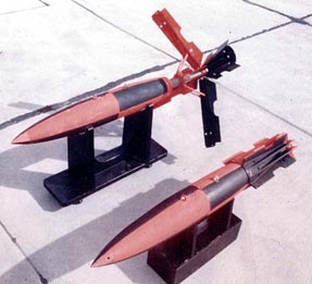
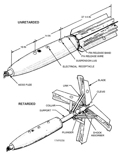
Snake-eye style retardation would be much sexier!How feasible would a self-deploying parachute be? If the 'chute was bright orange and relatively large (1'x1'), it could work pretty damn well. The only problem is getting it to deploy at the right time.
That's probably less complicated than it looks... parts list for those with the electronic understanding of a deployed Snake eye?Here is a schematic for transmitter and receiver using the 433MHz modules.
I also did the PCB layout for the transmitter. Perf board type and etched PCB type.
If someone wants the ExpressPCB files let me know.
A level switch could make sure it doesn't deploy before it reaches a certain angle towards the ground, hmmm...do some math and set it to deploy the chute about 5 seconds before predicted contact with the ground
There are photos of both sidesdewey-1 wrote:What about a picture of other side of PCB?
This will determine if board can be narrowed.
Good point. I can tolerate 20mm, my plan is to fit two AAA batteries in line that would provide power and ballast.Almost all RF tags will be about 20 to 25mm in width due to typical CR2032 battery being used which is 19mm.
Sorry. I actually meant to say a closeup photo of both sides to zoom in for better resolution. You can send high resolution images to my e-mail.jackssmirkingrevenge wrote:There are photos of both sidesdewey-1 wrote:What about a picture of other side of PCB?
This will determine if board can be narrowed.
The bit we think is the antenna is actually marked "ANT 2" in the first photo, relevant?
Good point. I can tolerate 20mm, my plan is to fit two AAA batteries in line that would provide power and ballast.Almost all RF tags will be about 20 to 25mm in width due to typical CR2032 battery being used which is 19mm.
Is it feasible to reproduce this circuit ?The device described in World War II patent[15] works as follows: The shell contains a micro-transmitter which uses the shell body as an antenna and emits a continuous wave of roughly 180–220 MHz. As the shell approaches a reflecting object, an interference pattern is created. This pattern changes with shrinking distance: every half wavelength in distance (a half wavelength at this frequency is about 0.7 meters), the transmitter is in or out of resonance. This causes a small oscillation of the radiated power and consequently the oscillator supply current of about 200–800 Hz, the Doppler frequency. This signal is sent through a band pass filter, amplified, and triggers the detonation when it exceeds a given amplitude.
Yeah I meant for a different projectile, MiniBoy is too small for just about anything.POLAND_SPUD wrote:for miniboy ?? I don't think that's feasible but if we're talking about cheap, simple and easy to build projectiles (something I suggested months agoIf the 'chute was bright orange and relatively large (1'x1'), it could work pretty damn well. The only problem is getting it to deploy at the right time) then I guess it wouldn't be very difficult
do some math and set it to deploy the chute about 5 seconds before predicted contact with the ground