Page 5 of 6
Posted: Mon Jul 02, 2012 8:51 am
by dewey-1
Use the 3 Volt relay and it will be much easier to incorporate and have less components involved.
I will redo the schematic for you with that relay.
Posted: Mon Jul 02, 2012 8:54 am
by wyz2285
One thing I forgot to mention, I couldn´t find a 10v 100uf cap, instead I got a 16v 100uf cap, is it ok to use?
Posted: Mon Jul 02, 2012 9:11 am
by dewey-1
Yes that will be fine.
Because the leads on the relay are so fragile I will also post an image of how to wire so there is less possibility of damage.
You could use double sided foam tape to mount the relay inside the box.
Once everything is working you can use hot glue on the leads and relay pins to the relay body to prevent the relay pins from breaking.
Here is the data sheet link;
http://gfinder.findernet.com//assets/Se ... /S30EN.pdf
Posted: Thu Jul 05, 2012 6:48 am
by wyz2285
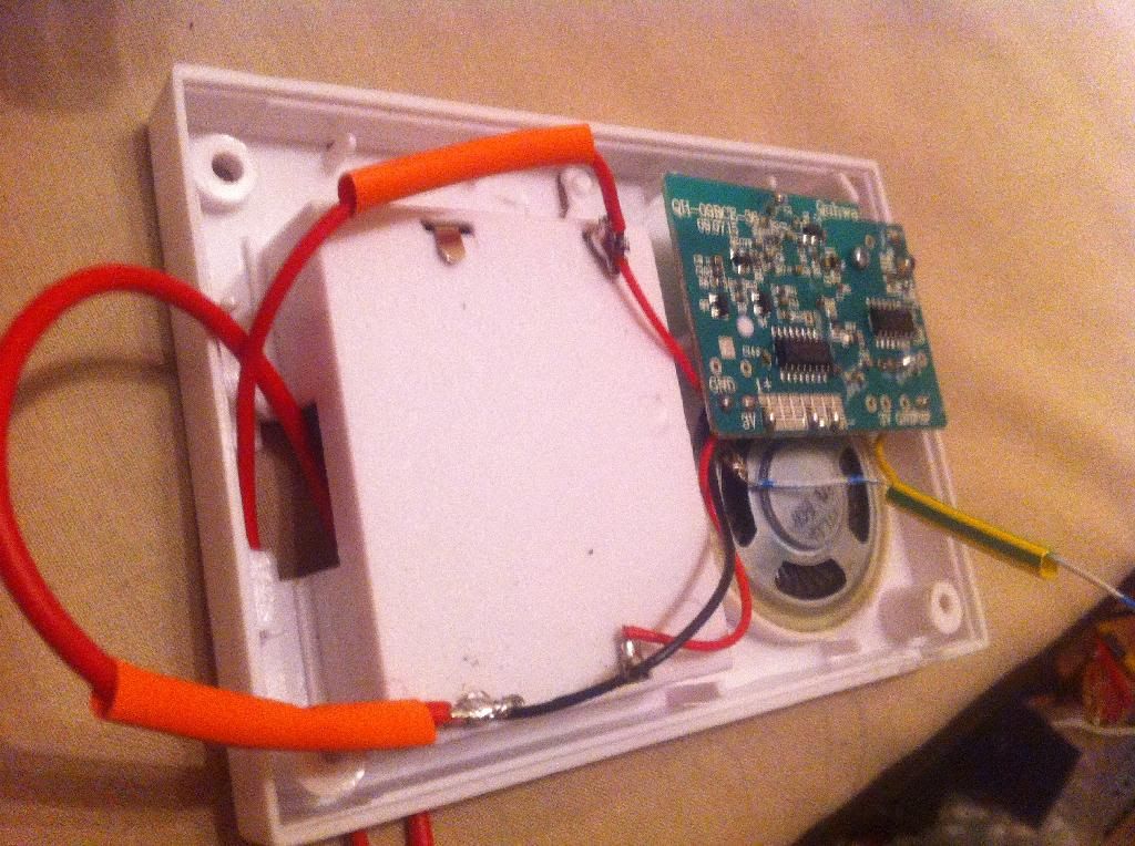
One question: what´s the wire connected to the negative of the capacitor? Battery negative?
Also I was planing fill the box with foam, is it a good idea?
Posted: Thu Jul 05, 2012 6:51 am
by dewey-1
Yes that is correct.
Posted: Thu Jul 05, 2012 7:37 am
by wyz2285
Something it´s wrong... again

The wiring should be right, but the relay isn´t activated, battery not strong enough?
Posted: Thu Jul 05, 2012 8:18 am
by dewey-1
You have it wired wrong! Recheck it versus schematic and pictorial I did.
Actually you have several errors. Give me a little time to edit one of your pictures to show how to correct.
Cut the Red and Yellow wire as shown. Cut the capacitor minus lead going to diode and capacitor +. The capacitor minus should only be going to the Black lead which is ground. The capacitor + lead should go to the Yellow lead connection.
Wire the Red lead to the diode white band and the Yellow lead to the other side of diode.
Edit relay pictorial Blue wire to pins 4 & 13 (wiper) instead of pins 8 & 9 (NO)
Posted: Fri Jul 06, 2012 4:42 am
by wyz2285
Ok, I have corrected the wiring. Still not working through

Posted: Fri Jul 06, 2012 5:10 am
by MrCrowley
Do you have a voltmeter? I don't have time to double check the wiring for you but if you have a voltmeter you can at least determine where the problem is. Is there sufficient battery power being supplied to the circuit? Is this power then sent through the 'speaker' wires when the doorbell is activated? Does this power reach the relay? Does the relay switch at all (you should be able to hear a click)? Are the NC contacts on the relay working properly in the default position (when the doorbell hasn't been activated)?
I had a brief problem where the diagram for a relay was wrong as it has mislabelled the contacts. Terminal 2 and 3 should've been NC with terminals 3 and 4 NO meaning I would wire the stungun through terminal 3 and 4 but instead it turned out I had to wire it through terminal 2 and 4 (which is counter-intuitive).
Posted: Fri Jul 06, 2012 6:29 am
by dewey-1
wyz;
Do not worry about the stun gun working yet.
As MrC stated, you should hear the relay clicking when the remote is actuated.
If not put the speaker back in to check if doorbell circuit still works. (without the relay/cap circuit)
You have been lucky so far that Q5 has not blown, but all these wiring errors may have finally damaged it.
Once you get the relay switching on and off then wire it up to the stungun.
The pictorial I did for MrC was wrong originally. The schematics were correct.
Here is the updated pictorial.
Re: How-to: remote ignition
Posted: Sun Dec 08, 2013 3:08 am
by vxrtol
The doorbell I picked up uses 3 x AA batteries. The circuitry only uses 3v with the other 1.5 topping up power to the speaker.
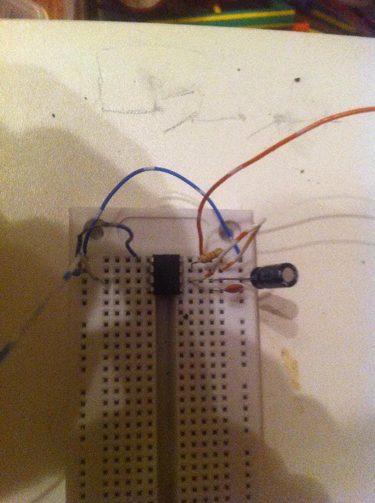
Due to me already having the components, I opted for a 555 monostable 'one shot' circuit triggered by the speaker voltdrop. I'm powering the 555 circuitry from the 4.5v meaning I'll get 3v output. Perfect for my camera flash circuit.
Problems and solutions
The on state of your 555 must exceed the duration of the trigger - if not the circuit will keep running until the ding donging stops. This greatly depends on your particular doorbells sounds and if your worried about how long the ignition circuit runs for. There is a solution by adding a few more components to the basic circuit that blocks subsiquent cycles. I'm mid soldering it onto a board but will post pictures of the finished project
Re: How-to: remote ignition
Posted: Sun Dec 08, 2013 10:31 am
by POLAND_SPUD
Ohh speaking of these. Once you have an arduino board you can use it as a programmer and then crete a standalone circuit using an ATtiny chip (cost ~$2) + a cheapo RF transmitter and receiver (
~$2, range about 100m) and a handful of passive components. Just wanted to point out that there are other methods
Re: How-to: remote ignition
Posted: Mon Dec 09, 2013 3:14 am
by vxrtol
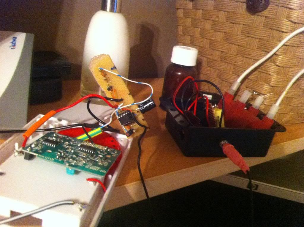
Almost there.
Receiver and 555 box outputs a single 3v 1 second pulse down a 3.5mm jack
Black HV box contains charging circuit, caps, spark gaps and coils.
Re: How-to: remote ignition
Posted: Mon Dec 09, 2013 7:23 am
by jackssmirkingrevenge
POLAND_SPUD wrote:Ohh speaking of these. Once you have an arduino board you can use it as a programmer and then crete a standalone circuit using an ATtiny chip (cost ~$2) + a cheapo RF transmitter and receiver (
~$2, range about 100m) and a handful of passive components. Just wanted to point out that there are other methods
0_0
Transmitter size 19mm x 19mm
Tell us more!
Can we make this thing track a projectile?
Re: How-to: remote ignition
Posted: Mon Dec 09, 2013 8:25 am
by POLAND_SPUD
Yeah, why not. You need a directional antennae for it but it goes without saying
Size isn't really much of a problem these days. You could build a much smaller transmitter using smd parts.
This guy's work is pretty impressive