Page 1 of 1
Before I solder
Posted: Sat Sep 12, 2009 1:25 pm
by boyntonstu

I want it to look similar to a Sten gun.
http://en.wikipedia.org/wiki/Sten_gun
It seems to me that a straight chamber to T path would be quicker than adding an elbow or two.
This design uses a 3/4 > 1/2 Fitting reducer installed backwards into the 3/4" copper T as the piston valve seat.
Using the fitting reducer is a copy of this gun:
http://www.youtube.com/watch?v=v-KvQD5nOXE
Theairgunman (George) has gone to 600 psi with his gun.
A few comments: The Schrader valve is redundant to the quick connect in case of a power outage.
Will the Schrader open beyond a certain pressure an act as a pop valve?
The pressure gauge is 0-600 psi.
My question is whether or not to add threaded fittings to tne barrel and chamber connections of the T? Lighter and more compact.
The only necessary screw access for piston maintenance is at the pilot end.
I do not plan on switching to smaller diameter barrels.
My plan is to use barrel inserts like this:

Comments, suggestions?
Thanks,
BoyntonStu
Edited by jrrdw.
Posted: Sat Sep 12, 2009 2:05 pm
by Technician1002
Nice design. I do have some comments.
The t design consideration was a good thought, but other considerations such as torque on the joints from recoil, handling and ease of use are primary reasons these are often made over/under. For flow, a chamber twice the diameter has 4 X the cross section, so for the same barrel flow, the chamber outlet would flow at 1/4 the speed for the same volume delivery. It may be worth considering an over under design with a larger diameter chamber and elbows necking down to your valve or even a larger valve. I have had very good performance with very short large diameter chambers.
A schrader does not perform like a pop off valve at all. They just tend to crack and vent like a relief valve at about 80 PSI. That is only for air blow in, they hold high pressure for air trying to get out.
At higher pressure the reducer you intend to use as a valve seat will have tremendous pressure on a narrow edge. This tends to punch circles in rubber valve seats. You may want to work on something with a little more surface area for a high pressure gun.
At higher pressure, something threaded is a good idea. materials change size and shape under stress and safety considerations must be given. Hose clams as shown are rarely used at high pressure above that used for irrigation. High pressure stuff is crimped metal collars.
I am building one too. Instead of over/under or a T, I'm building a coaxial. It will use a QDV piston.
Posted: Sat Sep 12, 2009 2:32 pm
by boyntonstu
Technician1002 wrote:Nice design. I do have some comments.
1 the t design consideration was a good thought, but other considerations such as torque on the joints from recoil, handling and ease of use are primary reasons these are often made over/under. For flow, a chamber twice the diameter has 4 X the cross section, so for the same barrel flow, the chamber outlet would flow at 1/4 the speed for the same volume delivery. It may be worth considering an over under design with a larger diameter chamber and elbows necking down to your valve or even a larger valve. I have had very good performance with very short large diameter chambers.
A schrader does not perform like a pop off valve at all. They just tend to crack and vent like a relief valve at about 80 PSI. That is only for air blow in, they hold high pressure for air trying to get out.
At higher pressure the reducer you intend to use as a valve seat will have tremendous pressure on a narrow edge. This tends to punch circles in rubber valve seats. You may want to work on something with a little more surface area for a high pressure gun.
At higher pressure, something threaded is a good idea. materials change size and shape under stress and safety considerations must be given. Hose clams as shown are rarely used at high pressure above that used for irrigation. High pressure stuff is crimped metal collars.
I am building one too. Instead of over/under or a T, I'm building a coaxial. It will use a QDV piston.
Thanks,
The 3/4 > 1/2 fitting reducer edge could be made thicker by soldering a 1/4" length of 1/2" copper tubing and smoothing the edge. Agree?
The barrel insert uses an O ring piston epoxied to the copper.
Should the hose clamps slip I can use several other designs to hold the insert with greater force.
Chamber diameter vs chamber outlet diameter.
If a 2" chamber is necked down to fit the 3/4" T, would the flow rate be higher than a straight 3/4" chamber.
My plan is to use 400-600+ psi as George has proven.
I plan on using a 38" long 3/4" (0.811") barrel. 19.58 cu in.
What length/volume chamber at 400 psi would suffice to accelerate a projectile 38"?
Thanks,
BoyntonStu
Posted: Sat Sep 12, 2009 2:51 pm
by jackssmirkingrevenge
Good to see you messing with a proper high perfromance pneumatic at last

boyntonstu wrote:What length/volume chamber at 400 psi would suffice to accelerate a projectile 38"?
As little as one cubic inch will be enough for a good shot, though if you're looking for every ounce of power make it as big as you're willing to live with, keeping in min that bigger chambers require more effort and make more noise.
Posted: Sat Sep 12, 2009 3:02 pm
by boyntonstu
jackssmirkingrevenge wrote:Good to see you messing with a proper high perfromance pneumatic at last
boyntonstu wrote:What length/volume chamber at 400 psi would suffice to accelerate a projectile 38"?
As little as one cubic inch will be enough for a good shot, though if you're looking for every ounce of power make it as big as you're willing to live with, keeping in min that bigger chambers require more effort and make more noise.
"As little as one cubic inch will be enough for a good shot, though if you're looking for every ounce of power make it as big as you're willing to live with, "
That is a very interesting comment.
What is the difference in power between a good shot from 1 cu in and the power from 10 cu in?
IOW What volume would cause the "Law of Diminishing Return" to kick in?
Increased fill time and a loud report comes from a chamber beyond what is necessary.
What length is necessary for the sweet spot shot?.
BoyntonStu
Posted: Sat Sep 12, 2009 3:20 pm
by jackssmirkingrevenge
I can only answer the above by plugging your launcher specs into GGDT and playing with chamber length, sadly I don't have it on this PC. Have you tried modelling it virtually?
Posted: Sat Sep 12, 2009 4:41 pm
by POLAND_SPUD
does it have to be a copper gun ?? IMO malleable iron fittings and pipes are the way to go....
sure building the valve would be more difficult and the gun would be heavier but you coudl easily mod the gun, use a different barrel or chamber... (or club someone with it)
Posted: Sat Sep 12, 2009 5:36 pm
by boyntonstu
POLAND_SPUD wrote:does it have to be a copper gun ?? IMO malleable iron fittings and pipes are the way to go....
sure building the valve would be more difficult and the gun would be heavier but you coudl easily mod the gun, use a different barrel or chamber... (or club someone with it)
I believe that copper may be safer than iron.
I prefer the way a copper pipe bursts.
Copper splits and stretches vs hand grenade iron shrapnel.
Soldered fittings can be reused, I've done it several times.
Also, with screw connections as an option, everything is replaceable.
There is also rust weakening to consider.
I would rather not see rusty iron.
In spite of the above, your cannon is very powerful and it works very well.
I salute your work.
BoyntonStu
Posted: Sat Sep 12, 2009 11:22 pm
by Technician1002
boyntonstu wrote:
Thanks,
The 3/4 > 1/2 fitting reducer edge could be made thicker by soldering a 1/4" length of 1/2" copper tubing and smoothing the edge. Agree?
Agreed. Smooth edges are a plus. Thicker in areas of stress and fatigue are a plus.
The barrel insert uses an O ring piston epoxied to the copper.
Should the hose clamps slip I can use several other designs to hold the insert with greater force.
Chamber diameter vs chamber outlet diameter.
If a 2" chamber is necked down to fit the 3/4" T, would the flow rate be higher than a straight 3/4" chamber.
Flow rate is often mis-understood. I had major problems with you can't go supersonic with just compressed air. The max flow out of a chamber through an orifice can only be sonic. That bugged me. At high pressure the air traveling sonic is more dense as it is at higher pressure. Bingo. More air mass goes through, but the speed is only sonic at max. Then it expands if unrestricted and goes SUPERSONOC. Woo hoo.
With that in mind a long chamber can empty out into a barrel at sonic speeds. A long chamber will have lower pressure at the transition. A shorter chamber larger in diameter will have less pressure drop going into the barrel. It seems possible the mass into the barrel will be faster, to then apply the pressure on the projectile.
My plan is to use 400-600+ psi as George has proven.
I plan on using a 38" long 3/4" (0.811") barrel. 19.58 cu in.
What length/volume chamber at 400 psi would suffice to accelerate a projectile 38"?
Thanks,
BoyntonStu
My recommendation is to work backwards from the desired pressure behind the projectile at barrel exit and work volume backwards.
Say minimum pressure that will still be accelerating at near 1100 FPS is 50 PSI due to windage, then figure the total volume barrel and chamber that will provide that exit pressure. Allow some more for flow resistance and the thermal change. GGDT will model the various chamber barrel combinations to provide the rough minimum chamber size. Some of my designs are showing gas temperature drops of over 100 degrees F.
Many of your other replies are excellent also. Too many to answer all in one post.
Some 2nd thoughts
Posted: Mon Sep 14, 2009 6:42 pm
by boyntonstu
I cast my first piston today out of Bondo.
I used a rubber foot that has a steel washer embedded in it.
The threads of a short screw are capture in the Bondo.
The piston is tight to the 3/4" ID and it is 1-3/8" in length.
It weighs about 1/2 oz.
(I discovered that a piece of 3/4" oak dowel about the same length but without the rubber washer and the small screw weighs about 1/4 oz.)
My question is whether there is enough clearance to fill from the pilot side?
Should I notch a line down the cylinder for equalization?
Will that tiny hole impede filling?
Or, should I fill from the chamber bottom?
I think that a return spring would be required if I filled from below.
BoyntonStu
Re: Some 2nd thoughts
Posted: Mon Sep 14, 2009 7:29 pm
by Technician1002
boyntonstu wrote:I cast my first piston today out of Bondo.
I used a rubber foot that has a steel washer embedded in it.
The threads of a short screw are capture in the Bondo.
The piston is tight to the 3/4" ID and it is 1-3/8" in length.
It weighs about 1/2 oz.
(I discovered that a piece of 3/4" oak dowel about the same length but without the rubber washer and the small screw weighs about 1/4 oz.)
My question is whether there is enough clearance to fill from the pilot side?
Should I notch a line down the cylinder for equalization?
Will that tiny hole impede filling?
Or, should I fill from the chamber bottom?
I think that a return spring would be required if I filled from below.
BoyntonStu
Always assume your piston leaks too much and only fix it if it leaks too little. Trust me on that one.
Re: Some 2nd thoughts
Posted: Mon Sep 14, 2009 7:40 pm
by boyntonstu
Technician1002 wrote:boyntonstu wrote:I cast my first piston today out of Bondo.
I used a rubber foot that has a steel washer embedded in it.
The threads of a short screw are capture in the Bondo.
The piston is tight to the 3/4" ID and it is 1-3/8" in length.
It weighs about 1/2 oz.
(I discovered that a piece of 3/4" oak dowel about the same length but without the rubber washer and the small screw weighs about 1/4 oz.)
My question is whether there is enough clearance to fill from the pilot side?
Should I notch a line down the cylinder for equalization?
Will that tiny hole impede filling?
Or, should I fill from the chamber bottom?
I think that a return spring would be required if I filled from below.
BoyntonStu
Always assume your piston leaks too much and only fix it if it leaks too little. Trust me on that one.
Leaks too little, as in not filling the chamber fast enough?
Believe me, I trust you.
Re: Some 2nd thoughts
Posted: Mon Sep 14, 2009 7:44 pm
by Technician1002
boyntonstu wrote:
Leaks too little, as in not filling the chamber fast enough?
Believe me, I trust you.
Leaks too much as in getting the hissssssssss without the boom. This is a very common problem here. "It won't fire, It just hisses and leaks the air out."
Posted: Thu Sep 17, 2009 6:57 am
by boyntonstu
Starting out with a 3/4>1/2 Fitting reducer (3/4 goes INTO fitting not onto pipe) cut it down to share solder region of T with 3/4" barrel.
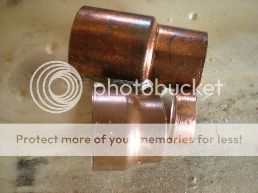
This is the complete seal with the sealing edge reinforced and fine sanded.

I used a tubing cutter to make o ring grooves in a short piece of 3/4" oak.
The rubber chassis foot with a steel washer embedded inside is the seal.
Notice that I am using the convex end to seal.

Painted and completed piston. I over sized the hole and used hot glue to hold the screw. I centered the rubber before the glue set.
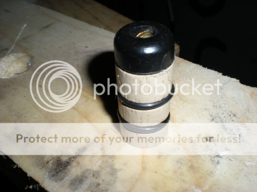
It slides very smoothly inside 3/4" copper pipe.
We will see how well it works.
I hope that the photos explain what to do to make one.
I believe that the oak is lighter than epoxy or Bondo.
I can drill a partial hole from the rear to make it lighter and/or to install a bumper or a return spring.
BoyntonStu
Posted: Thu Sep 17, 2009 12:37 pm
by Technician1002
@boyntonstu Very nice work. I like the wide valve seat. I was considering soldering on a pipe cap and drilling it out to the ID of the pipe to make a seat that is less likely to cut the seal. Well done and great photos.