Home made pressure regulator design
Posted: Wed Jul 04, 2007 11:29 pm
Regulator design
i was going to attempt to build this for my semie before i figured our i would still need a very large heavy metal chamber and pumping it up to 260psi would take forever. this could be used on guns with a smaller chamber or mabey a bb vortex gun. this allows you to have a chamber under 1/2 the size of a un-regulated chamber of the same output pressure.
After seeing a animation of a paintball reg in us snipers paint ball animation thread I was inspired to design one. The regulator animation: http://www.ultratwistedpaintball.biz/mm ... ulater.gif
Explanation of how regulators work
http://paintball.about.com/cs/airsystem ... lators.htm
Good site for true diameters of pipes and has a unit converter on the side bar
http://www.engineeringtoolbox.com/pvc-c ... d_795.html
us snipers paintball animations: http://www.spudfiles.com/forums/paintba ... t8364.html
Input pressure would by 260psi max output pressure would be 90psi.
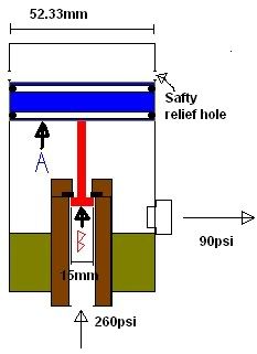
Above the piston (blue) is a spring this spring has to be able to be pushed up by 90psi but also move the poppet (red) down when it is under pressure from 260psi.
260 psi is from the charging chamber, the 90 psi gos to the firing chamber
CAUTION MATH!
Equations:
Pressure in 260psi 1793.103 N/mm squared
Pressure out 90psi 620.629 N/mm squared
Out put pressure acting on face of piston (A)
52.3 mm x pie = 163mm squared
163 x 620.63 N/mm = 101162.69 N (A)
Desired spring rate
Distance spring moves 20mm
101162.69 N
20 = 5058.1345N
5058.1345 N/mm Spring rate. 5058 Newton’s to compress the spring 1 mm
Max face area of poppet
1793.103 N x A = 101162.69 N
A=56.4 mm squared
Max diameter of poppet face
17.95mm
Diameter of poppet to be used
15mm x pie = 47
47mm x 1793.103 N/mm = 26896N (B)
Summery
To build a reg to regulate 260 psi down to 90 psi you will need:
• A airtight piston to fit in a 50mm pipe sh40
• A spring that can push with a force of 101162.69 N. To find out, multiply spring rate by distance. E.g Spring rate = 5058 N/mm spring is to be compressed 20mm so the force trying to make the spring expand is 20x5058=101160
• A poppet with a diameter of 17.95mm or smaller. I suggest not going above about16mm.
Other stuff
• Note: the brown bit on the diagram is copper and all bits holding 260psi are rated to that pressure or higher.
• The black bit near the poppet is a rubber washer.
• the poppet could be made out of a upside down bolt
• have a metal coin or something where the piston touches the poppet to stop it damaging the piston.
• By drilling holes at the required height you can also make it double as a safety valve. See safety relief hole on diagram. When the pressure gets too high the piston will move past this hole releasing pressure. Highly recommended I doubt sh40 can hold 260psi!
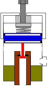
• To make adjustable have a bolt that can be turned to push the spring down. Positioned in 50mm end cap. The light grey bit with the light grey border is a nut
Closed
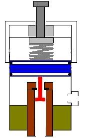
Open
feel free to ask any questions if you do not understand or point out any mistakes in my math
i was going to attempt to build this for my semie before i figured our i would still need a very large heavy metal chamber and pumping it up to 260psi would take forever. this could be used on guns with a smaller chamber or mabey a bb vortex gun. this allows you to have a chamber under 1/2 the size of a un-regulated chamber of the same output pressure.
After seeing a animation of a paintball reg in us snipers paint ball animation thread I was inspired to design one. The regulator animation: http://www.ultratwistedpaintball.biz/mm ... ulater.gif
Explanation of how regulators work
http://paintball.about.com/cs/airsystem ... lators.htm
Good site for true diameters of pipes and has a unit converter on the side bar
http://www.engineeringtoolbox.com/pvc-c ... d_795.html
us snipers paintball animations: http://www.spudfiles.com/forums/paintba ... t8364.html
Input pressure would by 260psi max output pressure would be 90psi.
Above the piston (blue) is a spring this spring has to be able to be pushed up by 90psi but also move the poppet (red) down when it is under pressure from 260psi.
260 psi is from the charging chamber, the 90 psi gos to the firing chamber
CAUTION MATH!
Equations:
Pressure in 260psi 1793.103 N/mm squared
Pressure out 90psi 620.629 N/mm squared
Out put pressure acting on face of piston (A)
52.3 mm x pie = 163mm squared
163 x 620.63 N/mm = 101162.69 N (A)
Desired spring rate
Distance spring moves 20mm
101162.69 N
20 = 5058.1345N
5058.1345 N/mm Spring rate. 5058 Newton’s to compress the spring 1 mm
Max face area of poppet
1793.103 N x A = 101162.69 N
A=56.4 mm squared
Max diameter of poppet face
17.95mm
Diameter of poppet to be used
15mm x pie = 47
47mm x 1793.103 N/mm = 26896N (B)
Summery
To build a reg to regulate 260 psi down to 90 psi you will need:
• A airtight piston to fit in a 50mm pipe sh40
• A spring that can push with a force of 101162.69 N. To find out, multiply spring rate by distance. E.g Spring rate = 5058 N/mm spring is to be compressed 20mm so the force trying to make the spring expand is 20x5058=101160
• A poppet with a diameter of 17.95mm or smaller. I suggest not going above about16mm.
Other stuff
• Note: the brown bit on the diagram is copper and all bits holding 260psi are rated to that pressure or higher.
• The black bit near the poppet is a rubber washer.
• the poppet could be made out of a upside down bolt
• have a metal coin or something where the piston touches the poppet to stop it damaging the piston.
• By drilling holes at the required height you can also make it double as a safety valve. See safety relief hole on diagram. When the pressure gets too high the piston will move past this hole releasing pressure. Highly recommended I doubt sh40 can hold 260psi!
• To make adjustable have a bolt that can be turned to push the spring down. Positioned in 50mm end cap. The light grey bit with the light grey border is a nut
Closed
Open
feel free to ask any questions if you do not understand or point out any mistakes in my math