I suppose I won't get too many responses to this but I'll ask anyway...
For future versions of BAGS I want to go beyond the "cookbook" equation for valve flow that I use in the current version. I have seen the "derivation" of this equation and it's fairly sketchy (see http://books.google.com/books?id=tlarCw ... 1&pg=PA341). I write derivation in quotes as its more of a justification than derivation. From this derivation you can see that the standard equation is based on steady state assumptions as it is based on the liquid flow Cv equation (which can be derived from Bernoulli's principle for steady flow). This equation might fit steady flow data well, but as we know the process is inherently not steady state.
(As a note, finding anything about deriving the standard valve flow equation was difficult. It seems that the equation is basically a black box to most who use it. They don't know how or why it works, just that it does work reasonably well.)
So I'm looking for an unsteady valve flow equation. Any leads?
Does GGDT use anything dissimilar to what BAGS uses at the moment? Based on this old post I'd say no (at least in 2004): http://www.spudfiles.com/spudtech_archi ... 865#p26865
I have on paper an implicit system of non-linear ODEs derived from the Reynolds transport theorem applied to mass, momentum, and energy conservation on some sort of constriction with extra terms for energy loss (due to viscous effects, valve poppet movement, etc.). These equations were derived without steady flow assumptions. As a note, implicit systems are really hard to solve.
I'm wondering if something this complicated is necessary, but I suppose I can't really know without comparing against simpler equations and real world data.
There's the problem of choked velocities. I've read in one book that for isothermal flow the Mach number choking occurs at is 1/sqrt(k) where k is the ratio of specific heats. If the enthalpy change over the valve is small as it should be, then the flow is approximately isothermal, so this might be a good approximation. I assume I can watch for when this occurs and if it does, appropriate changes are done to conserve energy while making the velocity through the valve equal to the choked velocity.
I still need to dig deeper into the mentioned book. If you want to, you can, as it's a free book: http://www.potto.org/downloadsGD.php
Valve flow equation derivation
Thanks for clearing that up.
The Reynolds transport theorem in this cases produces ODEs, not PDEs. Unfortunately the resulting equations are implicit and would probably be a pain to solve, but I'm up to the challenge. The resulting equations are piecewise approximations to the PDEs*.
I'll post my derivation. Perhaps you'll find it interesting or could point of a flaw.
* One can, with enough of these piecewise approximations, write CFD.
Last edited by btrettel on Sat Oct 31, 2009 12:34 pm, edited 2 times in total.
-
D_Hall

- Staff Sergeant 5


- Posts: 1949
- Joined: Thu Feb 07, 2008 7:37 pm
- Location: SoCal
- Has thanked: 13 times
- Been thanked: 48 times
Only problem with that is that now you'll need to start accounting for bends in the reservoir and other such phenom. At that point, just your user interface becomes a nightmare to write. If you're up to it, my hat's off to you!btrettel wrote:* One can, with enough of these piecewise approximations, write CFD.
That was just a side note. Unfortunately I accidentally deleted the sentence it was referring to before posting (It has since been corrected). For what I have immediately planned, no, I'm not doing that.
I wouldn't rule it out for the future. Finite volume methods are far more straightforward that the method of characteristics and have less problems than general finite difference methods (though mathematically there isn't much of a difference between finite volume and finite difference methods as far as I know--it's just that how you arrive there is different).
A 1D model is very adequate for many types of pneumatic guns. Bends obviously would have an effect, but from what I've read it's not always bad to treat the length down a segment of pipe with bends like a 1D flow as if it were straight. If I took friction into account I could approximate the effect of bends by making the friction higher where a bend would occur... but that might not be feasible.
I've been looking for a good way to solve the system of equations, but implicit systems are a huge pain in the ass to solve. I'm thinking a few simplifications or a change of variables are necessary...
I've been looking at this problem on and off for a few months, but I think I might have just found what I'm looking for.
The assumption that the valve has negligible volume returns unsteady equations identical to the steady flow model*. This is a significant simplification because as I had the equations earlier the flow into the valve and the flow out of the valve were not necessarily the same. So while assuming steady flow from the start is in general a bad assumption, here it returns a correct result.
I'll post the derivation for critique when I have a little more time.
* Note that as I use the conservation of mass, energy, AND momentum these aren't necessarily the same as what's used in GGDT. I'm not sure if D_Hall used the conservation of momentum.


Don't know exactly what you're up to, but am I way out in left field if I were to ask: Why not do it in time slices where each time slice is a frozen steady state flow and derive from the multiple answers? Or would that even make sense?
I see where you're coming from, but unfortunately that can't be done as you've said here and even if it could, it wouldn't solve the problem at hand. Thanks for posting your thoughts still.
Most simulations divide everything into discrete time slices (and space slices) as you've mentioned. That is how BAGS works. Each time slice is treated as constant values*, but they are not steady state values. Steady state means independent of time, i.e., that the output does not change with time.
This is why it's wrong to assume steady state from the beginning as the flow through the valve obviously will change with time, but here it doesn't matter as the "small volume valve" simplification reduces the equations to the same thing the steady state assumption does.
(Some steady state functions do depend on time in a loose sense--waves in electrical circuits or vibratory systems are good examples. However, there are also transient waves that die down. The steady state values are just what appears after a long time.)
Anyhow, the problem is that the result is a system of implicit equations. An example of an implicit equation is x = tan x. You can not write our what x equals explicitly (i.e., x = ...). You can make an approximate explicit equation, yes, but that's the best you can do. When you have a system of implicit equations like sin(x^2 + sqrt(x)) = cos y; y ^ 3 + sqrt(y) = 1 / x, the numerical methods involved to approximate the solution are inefficient unless you give them a particularly good guess to start.
* Many algorithms do not assume the values are constant in each time step. GGDT uses a third order approximation of the ODEs where each time step has smaller "substeps" in it. So this is only relevant to BAGS at the moment which uses the first order Euler method.
I just realized that I probably could neglect the highest order terms and get a good solution. As an example, say your time step is Δt. If a term of the equation contains Δt^3 and Δt is small (like 0.0001), then Δt^3 is much smaller. Neglecting higher order terms might result in a usable equation.


Are you referring to multiple dimensions Taylor's formula? I mean, what you're saying looks like limited developpments. (And perhaps Am i way off.. lol )
"J'mets mes pieds où j'veux, et c'est souvent dans la gueule."
Taylor expansions are the basis for a lot of numerical methods and for linearization of non-linear equations, so yes, they are relevant. The Taylor expansions of the terms I'm looking at can only be simplified by being replaced with zero (i.e. eliminated). Earlier I was not quite sure if this route was worthwhile, but it's a definitely possibility that I'll think about more now. Thanks.
Anywho, I'm going to wait until I have a good derived equation for valve flow before posting again, unless of course someone could lead me towards something usable. Post here if you can.
Anywho, I'm going to wait until I have a good derived equation for valve flow before posting again, unless of course someone could lead me towards something usable. Post here if you can.
Last edited by btrettel on Tue Nov 03, 2009 7:40 pm, edited 1 time in total.
-
Technician1002
- Captain

- Posts: 5189
- Joined: Sat Apr 04, 2009 11:10 am
That level of math is why I'm a technician, not an engineer. That stuff makes my head explode.  I do understand the concepts, but the math is beyond me. When you get it working, I would love to plug in some of my later cannons to see how the flow compared to a sprinkler valve of the same size. My real world in barrel accelerations have given me some insight into the assumptions GGDT makes and the low losses I am seeing. The model of the 2 inch valve with the 4 inch barrel and the light foam ball would be most interesting.
- Attachments
-
- 4 inch foam ball raw data.
How low are the losses you are seeing? Do they require a flow efficiency greater than 100%?
The equations I've developed have two ways to incorporate losses. One is the equivalent area of the valve (like what GGDT uses). The other is an energy loss coefficient. Hopefully this allows my equations to capture some features of the flow that would otherwise be ignored.
The equations I've developed have two ways to incorporate losses. One is the equivalent area of the valve (like what GGDT uses). The other is an energy loss coefficient. Hopefully this allows my equations to capture some features of the flow that would otherwise be ignored.
-
Technician1002
- Captain
- Posts: 5189
- Joined: Sat Apr 04, 2009 11:10 am
No I am not going over 100% to model this valve. I'm seeing close to 70-80% instead of 30-50 of many valves. I had to run the efficiency way up in GGDT to get it to model the exit velocities I was measuring.btrettel wrote:How low are the losses you are seeing? Do they require a flow efficiency greater than 100%?
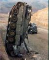
My graph is posted above if you would like to model it in GGDT. Starting from the muzzle, there are pick up coils spaced 1 foot apart along the length of the barrel. The magnet as it crosses the center of the coil transitions the polarity of the voltage from negative for entering the coil to positive for exiting the coil. The centerline crossing is the center of the coil. The first coil is not 1 foot from the projectile rest position. It is near it so it is moving as it passed the first coil. The test setup photo is below.
For those who wish to play with GGDT and the waveform in my earlier post, the 4 inch foam poof ball with the magnet installed tips my scale right at 2 oz or about 60 grams. The test shot is 60 PSI with 700 cu in of chamber volume. The barrel is 5.5 feet long. The valve is a QDV (not modeled in GGDT) with a 2 inch valve seat. The trace showing the time between the last two feet of barrel travel averages 454 FPS. I could not model this velocity in GGDT without raising the COF of the valve.
- Attachments
-
- 4 inch barrel test setup. Cannon, microphone mixer for a pre amp, scope, and printer.
-
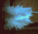
- Coil detail is seen on these two t shirt test barrels. The two are a 3 inch ABS and 2.5 inch PVC barrel with a muzzle break.
Create an account or sign in to join the discussion
You need to be a member in order to post a reply
Create an account
Not a member? register to join our community
Members can start their own topics & subscribe to topics
It’s free and only takes a minute
Sign in
-
- Similar Topics
- Replies
- Views
- Last post
-
- 8 Replies
- 3346 Views
-
Last post by sgort87
-
- 2 Replies
- 3539 Views
-
Last post by Gleedaniel13
-
- 7 Replies
- 2296 Views
-
Last post by sniper hero
-
- 1 Replies
- 1387 Views
-
Last post by POLAND_SPUD
-
- 16 Replies
- 4027 Views
-
Last post by singularity