No more piston slap!!... maybe...

Cannons powered by pneumatic pressure (compressed gas) using a valve or other release.
User avatar
Gippeto
First Sergeant 3
First Sergeant 3
Venezuela
Posts: 2504
Joined: Sat Jan 19, 2008 10:14 am
Location: Soon to be socialist shit hole.
Has thanked: 2 times
Been thanked: 17 times

All true.

I bought the oxy/map setup when I was installing the boiler/heating system in my house. Needed more heat than map alone to sweat the 1 1/4" stuff for manifolds and primary loop.

Wasn't going to shell out $300 (local price eh! :x ) and two more bottle contracts for that small of a job. The oxy/map setup was ~$90 here. :?

Would be a nice tool to have though....someday. :)
"It could be that the purpose of your life is to serve as a warning to others" – unknown

Liberalism is a mental disorder, reality is it's cure.
User avatar
Technician1002
Captain
Captain
Posts: 5189
Joined: Sat Apr 04, 2009 11:10 am

I bought a used welding set including regulaters, tanks, cutting torch, welding torch and tips, and some welding rods for about $100 a couple decades ago. Keep an eye open for retired folks and estate/tool sales.

I found mine in the classified ads in the paper (prior to Internet).

A good set will last a lifetime. Mine are so old the torch does not have flashback arrestors. I fully purge the lines before lighting it. Never had a problem. All torches were this way for a century.
User avatar
ThornsofTime
Private 4
Private 4
Posts: 88
Joined: Thu Oct 07, 2010 1:39 pm
Location: Texas

Ok... taking a few things that were mentioned and redesigned the valve

Lighter Bolt- Turned from plastic or aluminium
Less parts- Also cuts weight and troubleshooting
Less Labor intensive- Everything but bolt body is plug n play.

Thoughts??
Attachments
Valve in a Tee<br />(version 2.0)
Valve in a Tee
(version 2.0)
^(O_o)> Hi there
>(O_o)># I made you this waffle!
>(O_o)># then I remembered you were a dick.
(>#<) So I ate it.
User avatar
spudtyrrant
Corporal
Corporal
United States of America
Posts: 550
Joined: Fri Jan 02, 2009 6:10 pm

The pressure is not equalized in this design, the piston would just open as soon as you started to add pressure, along with this problem even if it was to work the piston isn't floating on the bolt, so you would probably get injured trying to use your hand to pull it.
User avatar
ThornsofTime
Private 4
Private 4
Posts: 88
Joined: Thu Oct 07, 2010 1:39 pm
Location: Texas

I think your thinking of this valve design as a typical piston type, where you have 3 ports: one barrel, one tank or pressure system with pilot valve, and one exhaust reservoir, similar to a QEV or sprinkler valve.

Its actually very closely related to technicians QDV as explained here.
http://www.spudfiles.com/forums/t-t17858.html

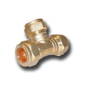
It differs in that: his is housed inside a tank, and mine is housed inside a Tee fitting.

The bolt wouldn't move as you begin adding pressure, the o-rings would catch and seal on the tubing that it sits in.

there is no "equalization of pressure" because the bolt/piston is operated manually (eliminating the need for a pilot valve because there is no pressure behind the bolt/piston)

concerning the o-rings, perhaps my drawing is inaccurate but the design does indeed call for floating o-rings in all 4 locations (creating a tight seal keeping air ONLY in the center of the Tee as depicted in the drawing... until you intentionally pull back the bolt that is.).

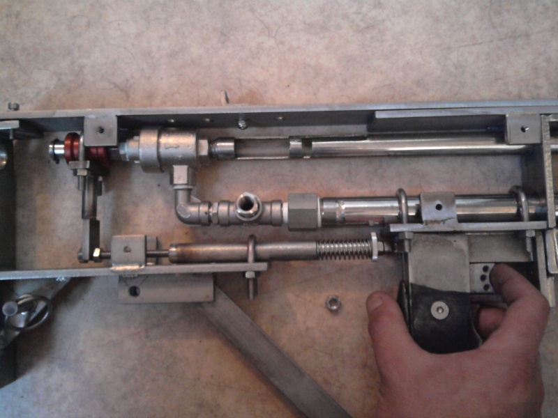
You are quite correct in your comment concerning operating this valve by hand... it would hurt... the all-thread is tapped into the bolt/piston and the whole assembly moves as a unit. However, it wasn't designed to be operated by hand. The steel lock-nuts on the end of the all-thread act as a ledge that a standard trigger assembly can press against, basically operating it remotely. Quite similar to the way this airgun engages the slide valve.
http://i39.servimg.com/u/f39/14/59/04/00/photo010.jpg

Please read and understand before posting. The picture clearly illustrates and says that its operated via trigger, among other things. Instead of just saying "WRONG" some thoughts as to how to fix the possible issues would have been nice. I dont mean to come off as a jerk, but I worry that others will be less likely to study my diagram once it has been discounted, and I truly want feed back (even if it does turn out to be a flop).

sorry for the wall of text
^(O_o)> Hi there
>(O_o)># I made you this waffle!
>(O_o)># then I remembered you were a dick.
(>#<) So I ate it.
User avatar
jackssmirkingrevenge
Five Star General
Five Star General
Posts: 26219
Joined: Thu Mar 15, 2007 11:28 pm
Has thanked: 582 times
Been thanked: 347 times

ThornsofTime wrote:Please read and understand before posting. The picture clearly illustrates and says that its operated via trigger, among other things. Instead of just saying "WRONG" some thoughts as to how to fix the possible issues would have been nice. I dont mean to come off as a jerk, but I worry that others will be less likely to study my diagram once it has been discounted, and I truly want feed back (even if it does turn out to be a flop).
He's actually right, due to the disparity in seal diameters (o-rings at the front and back of the "piston") there is a net force from the air pressure trying to push the piston back as hinted by the blue arrows, which means that as soon as you start to pressurise the piston will start moving back and open.
Attachments
piston.gif
piston.gif (19.05 KiB) Viewed 4166 times
hectmarr wrote:You have to make many weapons, because this field is long and short life
User avatar
Technician1002
Captain
Captain
Posts: 5189
Joined: Sat Apr 04, 2009 11:10 am

A guide for the "Floating" O rings are in order. When the valve opens, the pressure of air under the rings to provide sealing pressure will remove them from the groove and launch them at higher pressure. Been there, done that. Replacing the rings each shot gets old fast.

This is why I use ports. The sides of the ports prevent the o ring from lifting out of the groove.

I took the liberty to modify the drawing to fix the size issue that would open the valve when the chamber is filled and added the port to retain the o rings.

I did not take the liberty to fix the rod issue.

Another variation that could work well is to use a smaller diameter piston (will fit in the barrel) and extend the barrel through the T with traditional QDV ports cut in it. Either variation will work well. The larger valve in the drawing below will have lower pressure loss through the ports due to the large area and resulting lower velocity in the port area.
Attachments
Modified piston to fix unbalance.
piston_182.gif (17.98 KiB) Viewed 4141 times
User avatar
velocity3x
Corporal 4
Corporal 4
Posts: 828
Joined: Fri Jun 05, 2009 3:09 pm
Location: Yuma, Arizona
Contact:

It seems to me that as the piston retracts, pressure will build behind the piston and prevent or slow its opening unless a vent is provided in the aft section of the Piston housing but.....I could be wrong.
User avatar
Technician1002
Captain
Captain
Posts: 5189
Joined: Sat Apr 04, 2009 11:10 am

The simple way air pressure builds as the space becomes smaller makes this less of an issue than is normally assumed. Take a typical pressure of say 5 bar. Open the valve. At what point in travel does the piston balance and start slowing down? It is true as the pressure builds in the "Pilot" the acceleration will drop off, which is good.. it acts as a bumper spring. With a proper size vent, it works as a "Dashpot" with little recoil.

At 1/2 travel the pilot pressure will only go up 1 bar.. At this time the valve is pretty much wide open.
MRR
Specialist 3
Specialist 3
Posts: 361
Joined: Tue Feb 17, 2009 2:29 pm

Design suggestion:
Take a 3/4" male Tee-fitting, insert a pipe (barrel) that fits the Tee and secure it with two compression fittings (ports have to be cut before that).
Build a piston that covers the ports and use Techs actuation method by centre drilling the piston and using a slide rod.

No piston slap and you can also use a trigger mechanism if you want.
User avatar
ThornsofTime
Private 4
Private 4
Posts: 88
Joined: Thu Oct 07, 2010 1:39 pm
Location: Texas

@MRR- I THINK I understand what your saying. Is it really close to the modified diagram Technician made up?? Using his piston design you need a small space between the end of the piston and the barrel, to allow for a Nut on the all-thread that now passes thru the entire piston. Probably solved by just cutting off the pipe @ desired length and adding a reducer that matches barrel size.

Not sure I understand the compression fittings comment. I see a need to weld/solder the pipe to the tee fitting to keep the pipe in place, but could you further explain the compression fitting idea?? If it keeps the pipe in place without welding im ALLLLLL about it.

@JSR, Technician, Velocity3x, and MRR- Thanks for taking the time to examine and inform. I truly appreciate the feedback.

@Spudtyrrant- First off, I apologize for the dickish remarks. I truly didnt mean to come off that way. Too much 'Barney and friends' has my happy and nice quota satisfied for months to come. FOR THE RECORD- you were rite, I was wrong... I should have questioned before reverting to a$$hat mode.

EDIT- would there be any advantage in scaling this model down to say... a 1/2" design?? Allowing the tube that houses the piston to BE my barrel instead of using a reducer fitting to end up where I want to be barrel wise?? I would think it wouldn't matter since the barrel is a constant, not a variable, and will have the same rate of flow either way. Basically... is there a benefit to having a larger "air in" than your "air out".... or is it just a efficient to have "air in" and "air out" the same size so long as the port between them is sufficient??
Attachments
ValveInATee2.jpg
ValveInATee2.jpg (36.56 KiB) Viewed 4098 times
^(O_o)> Hi there
>(O_o)># I made you this waffle!
>(O_o)># then I remembered you were a dick.
(>#<) So I ate it.
MRR
Specialist 3
Specialist 3
Posts: 361
Joined: Tue Feb 17, 2009 2:29 pm

Compression fittings are used to connect metal pipes with screw fittings without soldering.

Image olive --> Image

You put the "olive" and the cap over the pipe and screw it into the tee fitting. The olive deforms and makes a very strong connection with the pipe, keeping it in place.

Edit: Just saw your diagram and thats the way to go!
User avatar
ThornsofTime
Private 4
Private 4
Posts: 88
Joined: Thu Oct 07, 2010 1:39 pm
Location: Texas

So... with a compression fitting I use SMOOTH pipe, NOT pipe with threaded ends rite?? And does this fitting have the ability to slide a solid pipe ALL THE WAY THRU the tee?? then just use two olives on each end to pinch it in place??

all of my experience is with standard pipe thread joints or flare fittings. Never messed with a compression. :D :D
^(O_o)> Hi there
>(O_o)># I made you this waffle!
>(O_o)># then I remembered you were a dick.
(>#<) So I ate it.
User avatar
c11man
Corporal 3
Corporal 3
Posts: 783
Joined: Fri Feb 06, 2009 4:37 pm
Location: Wisconsin, USA

yes, unthreaded pipe is used with compression fittings. a unmodified fittting has a stop built in to prevent the pipe from going on the way though, get the right size drill bit and a drill press and you can easily modify it to work
Post Reply

Create an account or sign in to join the discussion

You need to be a member in order to post a reply

Create an account

Not a member? register to join our community
Members can start their own topics & subscribe to topics
It’s free and only takes a minute

Register

Sign in

  • Similar Topics
    Replies
    Views
    Last post