Jimmy I am trying to make this beast sound leathal even if it has no ammo.. bascially a point and shoot and BANG (electric) then if i decide to shoot it.. i can do that too.. i have it wired up.. just like above.. ecept i have 8 capacitors + to + and - to - .. when they touch together once charged.. this think is seriously louder than a 22. pistol.. for real and has about a 2 inch in diameter round spark come off it..
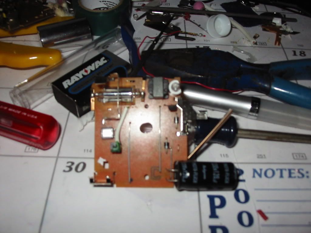
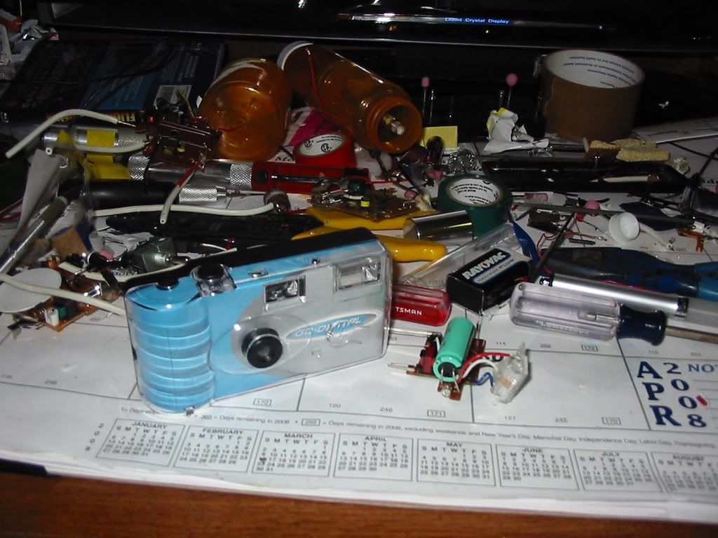
circuit one from target (kodak)
circuit 2 (polaroid)
circuit 3 (fugi)
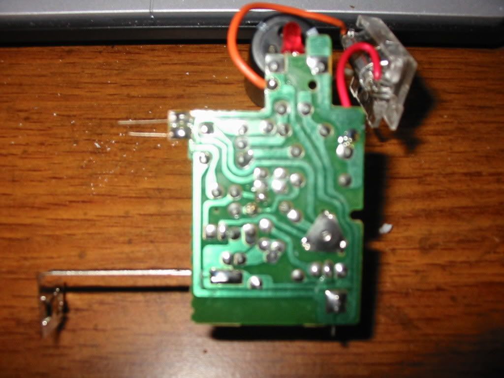
and my favorite.. circuit 4 (the one I think is made for spudding) (offbrand)
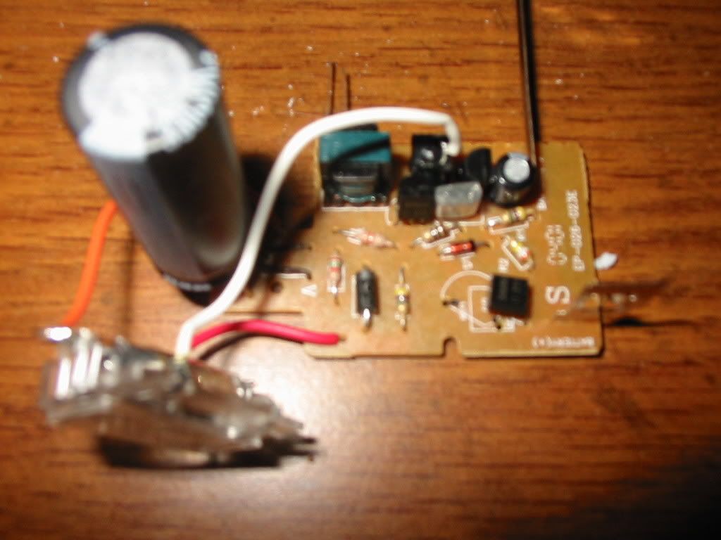
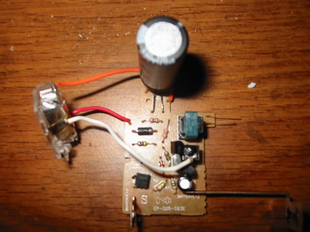
no name brand camera and its board
do you guys agree that 4 would be the best choice? look how the wiring to the flash is...
Yep, it looks like #4 would be the easiest to mod. Of course, I don't know anything else about the circuit so it is kind of hard to say if there are any significant electrical differences.
So, you ran wires (+ to +, minus to minus) across several of the circuit boards. Took some more wire and ran from the + and - to a spark gap. You then took one of the boards and are using it's HV trigger to fire the spark gap?
Are all the boards the same?
I think I would use a single board as the charger. Remove the caps from several other boards (preferably of the same type so the caps match) and slave'm to the one board. Wired as you've already described, + to + etc.
Since multiple caps are gong to suck a lot of juice from the battery you might consider replacing the AA (AAA?) with a C or D battery.
I would take the voltage/current off the caps themselves and not off the flashboard's connections to where the flashtube was. The copper trace on the board probably won't handle much more than a single cap during discharge. (It should be OK during charging.) Heck, you might as well take all the caps and mount them on something like a small piece of perf board, then run wires from the circuit board to the cap board to charge the caps. As above, take the output from the caps from the caps themselves and not the flash circuit board.
The energy stored in a capacitor is given by;
E = (0.5)CV<sup>2</sup>
Where energy is in Joules, C in farads and V in volts.
Wiring capacitors in parallel (as you are doing) gives an effective capacitance that is the sum of the individual capacatances. So, 3 caps store three times the energy as a single cap (and will take 3x longer to charge and use 3x more juice out of the battery.) The voltage across each cap is the same as for a single cap, roughly 300V for most of the flash boards.
If your cap is 120MFD (a typical size for these boards) and charged to the typical voltage of ~300V then there is 5.4J of energy in each cap.
Do you have a voltmeter that will read up to 300V DC or more? That's an easy way to monitor the charging of the cap(s).
Sometimes removing the "ready" light (which is either a neon-2 bulb or an LED) will increase the maximum voltage that the board will charge to.
Sounds like fun, but be careful. There is probably enough energy in a several photocaps to kill you, especially if the current flows across your heart. That is what happens if you touch the wrong things with both hands at the same time.
jimmy101 wrote:Well of course the board caught fire, that's part of the "fun".
Actually, the board shouldn't catch fire. How many caps you got wired up to this thing right now? The copper traces on the board were designed to handle the current from a single cap, if you've got several caps all slaved to the same board then ... who knows what'll happen.
Y'know I think jimmy's right on that.
You were shorting out the cap THROUGH the circuit board so all the current had to go through the thin copper foil on the board which isn't going to be too happy about the extra energy.
If you use proper wires directly from the capacitor as I did then it should be ok.
_Fnord wrote:Do photoflash caps really run at 300v? I've never been able to get my cap banks up past ~270, which is closer to 4.7.
Normally they don't.
I know the LED's light up somewhere around 220V.
However with my minature stripped down charging circuit running on 1 AA battery I can do this:
It actually reaches 345V but the small but significant drain from the meter lowered it before I could take a picture.
_Fnord wrote:Do photoflash caps really run at 300v? I've never been able to get my cap banks up past ~270, which is closer to 4.7.
Not that it matters. Just wondering.
Actually, I think most will get to 330V. Basically the circuit will charge up to the voltage limit of the cap. If it's a 300V cap then it'll charge up to that. A 330V cap will get to 330V.
There are some caveats:
1. This is what the Kodak board does, the one I have the most experience with. I'm not sure how other boards behave. There are some significant differences in the circuitry of the various boards.
2. It helps if you remove the "ready" light from the board. The Ne-2 or LED light puts a significant load on the circuit and will keep it from charging the cap all they way to the maximum. Like Hotwired posted, even the very high impedance load (~10 MegOhm?) of a digital voltmeter is enough to pull the voltage down.
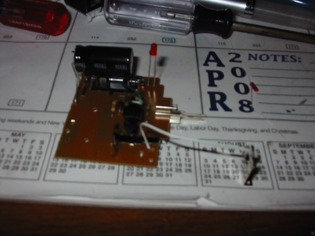
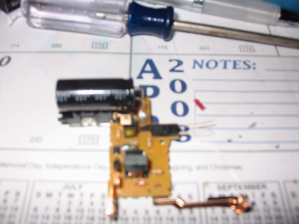
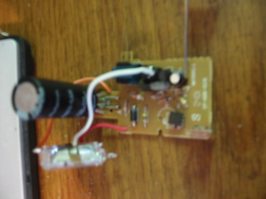
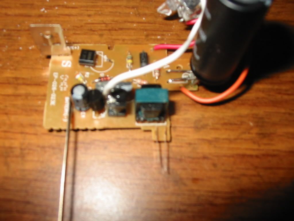
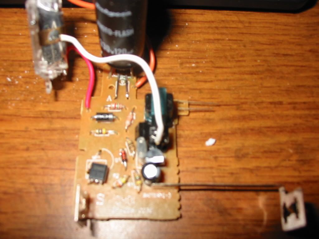
Okay.. im gonna show you some pics of the ciruit i am going to build with.. and keep you informed with pictures as i go.. but this is the circuit..( i scraped the kodak one due to continually burning boards..)
photos follow.. of the board i am gonna use.. i like this one cause it has several resisters.. which is better then the No resister take on the kodak
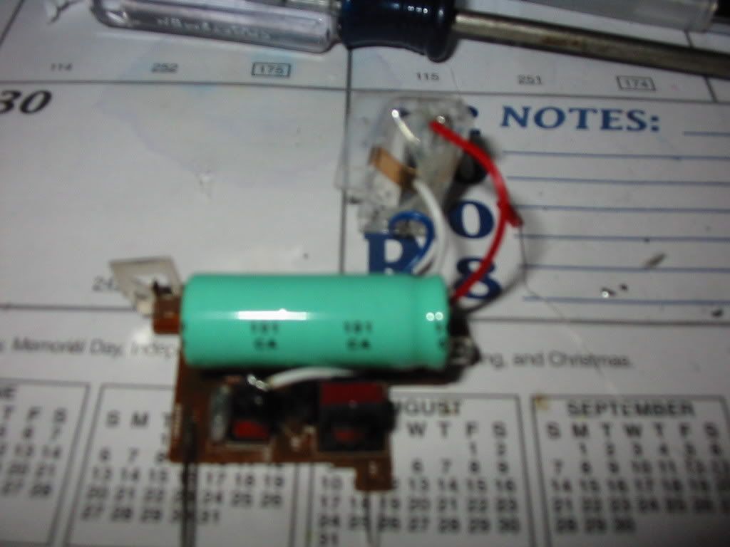
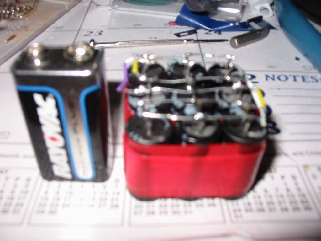
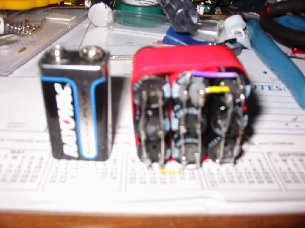
okay.. here is photos of the capacitor bank i am going to use..keep in mind.. i was using 8.. and now i am using 9.. i have encluded a 9 volt to show you relitivity in size.. as i am trying to keep this small so it can go in a little project box on my gun..
jimmy101 wrote:
2. It helps if you remove the "ready" light from the board. The Ne-2 or LED light puts a significant load on the circuit and will keep it from charging the cap all they way to the maximum.
Actually if you look closely at the picture I've got a "reached 220v+" LED in there, you can just see the glow in the pink wax filled circuit case under the topmost white test lead.
Edit: Scott the readings were from 0 to over 1000
Clamp the leads on with little crocodile clips or any kind of clip for a stable reading
Edit: I like my meter, it's got no fiddly dial, just one position for AC and one for DC. Both read 0-1000V
What would happen.. or should i say would it be better if i put a diode on the positive and the negative side of the board going into the capacitors to keep any energy from coming back into the board from the capacitors.. esentially trapping it on the capicotr side instead of it leaking onto the board...
then run leads from the capitor to my spark gap.!//
what do you think? and what did you think about above videos.. on voltage for 9 of these little beautys..
The energy is all stored in the capacitors anyway, any problems you have with the board catching fire/melting etc is because the energy is getting routed through the thin copper film on the way to the spark gap.
Take the power wires directly from the capacitor bank and when you discharge it in a spark none of it goes through the board.
I think it should be fine, I can't make up my mind exactly what voltage your bank is at until you can get a stable reading
Ive actually found better luck doing a triangular formation. I dont think you want to use this method, the electrodes corrode very fast (with 1 cap)and need replacing/repositioning after a few shots.
Your video of the spark seems kinda small, or bad camera (UV).
i am having a incrediabley hard time getting the gap right.. would it be better if I used a ring for the center wire.. instead of a point?
A ring would not work, the electrodes (outer ones) would be to far out, so the HV spark will not ioznize the air.