dewey-1 wrote:Tech;
What is your equalization hole size in your 2" piston? I am guessing around
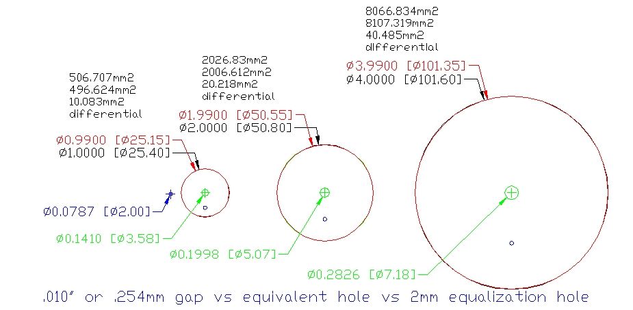
.0625" to .080". (1.59 to 2.00 mm)
I may do another drawing to show a .25mm or .010" gap for a more realistic picture.
My 2 inch piston is a QDV, so the piston is not using a pilot. The pilot area is never under pressure, so it can't be vented to fire the cannon. The QDV valve seat and piston OD is the same size.
The Mouse Musket is using a 1 inch barrel, so the piston is 1.5 in diameter. The EQ hole is 1mm.
The Mouse Musket is a 1 inch barrel 2 inch chamber coaxial. The piston rides in a very short length of 1.5 inch pipe in a 1.5 inch female adaptor swedged into the end of the 2 inch chamber. This is built that way to make the piston ratio a close ratio piston as the valve seat is larger than the bore of the barrel. The valve seat is an o ring on the outside of the barrel held in place by a coupler grooved to hold the ring.
Until it broke and I built the QDV, this was my best performing cannon. It put 1 inch gumballs through 1/2 inch sheets of plywood. The valve is very fast and opens with a POW.
The Dragon cannon, my other piston cannon is 2.5 inch porting with a 3 inch piston in a 6 inch chamber. A reducer is used to reduce the 6 inch to 4 inch. A female 3 inch adapter was used to hold the 3 inch section of pipe in the adapter for the piston, so the dragon is another close ratio piston. Due to the size, it tended to either not work or break things. An inverted 2.5 inch pipe cap was used for pistons. The PVC didn't like the forces and pistons were short in life expectancy. This cannon is retired due to the difficulties keeping it working. The Dragon used an o ring in the piston cylinder for a seal instead of on the piston.
A 3 inch QDV in a propane tank will replace the Dragon.