For the higher voltage trigger devices, the "Gas Discharge" spark gap. They are often Argon instead of Neon for a much lower on resistance and higher voltage break over voltage. They are used to protect the electronics that drive CRT (display tubes) televisions and monitors. If you have an old monitor, look for something that looks like neon bulbs on the CRT socket PCB.
As stated earlier, a Diac (bi-directional trigger diode) will work fine. Use a larger trigger cap as these typically break down (fire) at about 20 volts. They are used in cheap light dimmers. A typical light dimmer circuit is below. You don't want to fire 120 times a second, but you do want the trigger current, so use the recommended trigger cap (47nF) but greatly increase the charging resistor value to increase the charge time to your required delay of .1 seconds or longer. Start at 1 megohm and adjust from there as needed. http://www.electronics-project-design.c ... rcuit.html
Thanks Tech, but I've got my circuit ready to be jumpered up and tested at the moment. It was giving me fits laying all the components out on perfboard so that there were fewer "spaghetti monsters" and to where it would fit in a 2" SCH-40 enclosure.
I wound up making two circuits. Not because I thought two circuits would be nice, but because I fried the first one (more on that later).
Anyways, the board measures about 1.5x2.25", takes any voltage from 12 to 35 volts DC, and produces a pulse of ~370 VDC when the trigger leads are shorted (running at ~12 VDC). SCR works like a charm.
Back to the first circuit. I am using a power supply consisting of two 6V gel-cell batteries wired in series. I was flipping the first circuit over when powered to check something with my multimeter, and the arming switch shorted across the positive battery cable, causing much smoke and alarm. No incidents the second time around, though...
I also have a smaller ignition coil from an ATV which produces slightly lesser results than the big coil, but still plenty for a multipoint ignition.
Thanks to everybody for all the help, although, in the end, a single-shot igniter is the best I can hope from my limited electrical skills. If anybody would like the final circuit diagram I could draw it up (it changed somewhat).
EDIT: agh, I'm going to apply a bead of epoxy or liquid tape at the bottoms of all the wires this morning. I was attempting to get a few untangled and one broke off, requiring me to wait for my soldering gun to reheat, solder one joint, and then wait for it to cool down so I could put it away.
Other than that, though, you'll see this mounted in a cannon sometime in the future. Keep it fresh.
Attachments
A boatload of wires, but they all have a purpose. They will be trimmed down when the circuit is mounted in a launcher.
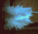
I was too lazy to measure this gap, though I'm positive it can jump a bit more.
I'm trying to get a new ignitor, because my current one...broke. I'm going to use the camera flash method. I have a good idea of what to do, but just...
Last post
Very informative video...
Well it's Halloween so I have to do things (guard the house, lead little sisters around nieghborhood, et cetera) so I'll...